How to choose an LED resistor
How the LED resistor is calculated
R = (Vs − n × Vf) / I
An LED is not a resistor: once its forward voltage Vf is reached, the current rises almost without limit. A series resistor takes the leftover voltage and sets the current. Subtract the LEDs' forward voltages from the supply, then divide by the current you want.
Typical forward voltages at 20 mA: red and orange about 2.0 V, yellow 2.1 V, green 2.2 V (pure green up to 3.2 V), blue 3.0 V, white 3.1 V, UV 3.3 V, infrared 1.3 V. A standard 5 mm LED is rated 20 mA continuous; 10 mA is often bright enough.
The exact result is rarely a value you can buy, so the calculator rounds up to the next E12 value: the LED then runs slightly below the target, never above it. The resistor power is P = U × I, and the suggested rating keeps a 2× margin so the part stays cool.
Worked example: three white LEDs on 12 V
You want to light three white LEDs (Vf ≈ 3.1 V) in series from a 12 V supply at 20 mA.
- Voltage left for the resistor
12 − 3 × 3.1 = 2.7 V - Exact resistance
2.7 V / 0.020 A = 135 Ω - Next E12 value up
150 Ω → I = 2.7 / 150 = 18 mA - Power in the resistor
2.7 V × 0.018 A ≈ 49 mW → 1/8 W
Use a 150 Ω resistor: the string draws 18 mA and a 1/8 W (or the common 1/4 W) resistor is plenty.
Common mistakes
One resistor for several parallel LEDs
LEDs never have exactly the same Vf: the one with the lowest voltage hogs the current and dies first. Give every parallel string its own resistor.
Rounding down instead of up
Taking 120 Ω instead of 150 Ω in the example above pushes the current to 22.5 mA, above the LED's rating. Round up to stay safe.
Leaving no voltage for the resistor
Four white LEDs need 12.4 V on their own, so a 12 V supply cannot light them. Keep at least 1 V to 2 V across the resistor so the current stays stable when the supply or temperature changes.
Using the high-power LED figures for a 5 mm LED
A 1 W power LED is meant for 350 mA with a heatsink; a standard indicator LED is 20 mA. Check the datasheet of the part you actually have.
LED resistor FAQ
For a red LED (2 V) at 20 mA: (5 − 2) / 0.02 = 150 Ω. For a blue or white LED (3.1 V): (5 − 3.1) / 0.02 = 95 Ω, so 100 Ω. 220 Ω is a safe default that gives about 10 mA to 14 mA.
One red LED at 20 mA: (12 − 2) / 0.02 = 500 Ω, so 560 Ω, dissipating about 0.18 W, which calls for a 1/2 W resistor. Putting several LEDs in series wastes less power in the resistor.
No. The pin would try to drive far more than its 20 mA recommendation and can be damaged along with the LED. A 220 Ω to 330 Ω resistor is the usual choice on 5 V boards, 100 Ω to 220 Ω on 3.3 V boards.
It does not matter: in a series loop the same current flows everywhere. Put it on the anode or cathode side, whichever is easier to wire.
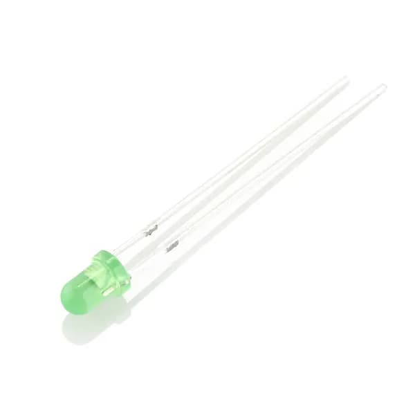
The longer leg is the anode (+). On the body, the flat edge of the rim marks the cathode (−), and inside the LED the cathode is usually the larger piece of metal.