How to pick the right pins
How to read a pinout
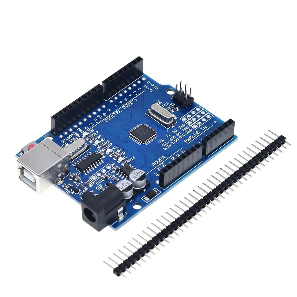
Most pins do several jobs. On the Arduino Uno, the pins marked ~ (3, 5, 6, 9, 10, 11) give PWM, A0 to A5 are analog inputs, I2C is on A4 (SDA) and A5 (SCL), SPI on 10 to 13, and 0/1 are the serial port shared with USB.
The ESP32 can route most functions to almost any GPIO, but not every pin is free. GPIO 6 to 11 are wired to the flash memory, GPIO 34 to 39 are input-only with no pull-up, and GPIO 0, 2, 5, 12 and 15 are strapping pins read at boot, so a circuit that pulls them the wrong way stops the board from starting.
The two boards also differ electrically: the Uno works at 5 V with a 10-bit ADC (0 to 1023), the ESP32 at 3.3 V, its pins are not 5 V tolerant, and its ADC is 12-bit (0 to 4095). ADC2 pins cannot be read while Wi-Fi is on.
Worked example: wiring a Wi-Fi weather station on an ESP32
You want to connect a BME280 sensor (I2C), a potentiometer and a dimmable LED to an ESP32 that sends data over Wi-Fi.
- Sensor on the default I2C pins
Wire.begin(21, 22); // SDA, SCL - Potentiometer on an ADC1 pin (works with Wi-Fi)
int value = analogRead(34); // 0–4095 - LED on a free PWM-capable GPIO
ledcAttach(27, 5000, 8); ledcWrite(27, 128);
GPIO 21/22 for I2C, GPIO 34 for the potentiometer (input-only is fine for reading), GPIO 27 for the LED, and no strapping or flash pins used, so the board always boots.
Common mistakes
Reading an ADC2 pin with Wi-Fi on
On the ESP32, analogRead() on GPIO 0, 2, 4, 12 to 15 and 25 to 27 fails while Wi-Fi is running. Use ADC1 pins (GPIO 32 to 39) for analog inputs.
Driving an output from GPIO 34 to 39
These pins are input-only and have no internal pull-up or pull-down. A button on them needs an external resistor.
Connecting 5 V signals to an ESP32
ESP32 pins take 3.3 V at most. A 5 V sensor output or an Arduino pin needs a level shifter or a voltage divider.
Using D0 and D1 on the Uno
They are the serial port shared with USB: anything connected there can block uploads and garble the Serial Monitor. Keep them free unless you need hardware serial.
Pinout FAQ
Pins 3, 5, 6, 9, 10 and 11, marked with ~ on the board. analogWrite(pin, 0…255) sets the duty cycle.
On the Uno, SDA is A4 and SCL is A5 (also repeated next to AREF). On the ESP32 the defaults are SDA GPIO 21 and SCL GPIO 22, but Wire.begin(sda, scl) can use other pins.
GPIO 6 to 11 (flash memory), and with care the strapping pins 0, 2, 5, 12 and 15. GPIO 34 to 39 are input-only. GPIO 1 and 3 are the USB serial port.
The Uno: 20 mA recommended per pin, 40 mA absolute maximum. The ESP32: about 20 mA recommended per pin, 40 mA maximum. For motors, relays or LED strips use a transistor or MOSFET.
A strapping pin (often GPIO 12 or 0) is being pulled the wrong way at power-on. Move that connection to a free GPIO, or make sure the circuit leaves the pin at its default level during boot.