How ADC readings and number bases work
From a raw reading to volts
V = reading × Vref / 2ⁿ
An n-bit ADC divides the range from 0 V to its reference Vref into 2ⁿ steps. A reading is the number of the step the input falls into, so the pin voltage is reading × Vref / 2ⁿ and each step (one LSB) is Vref / 2ⁿ wide.
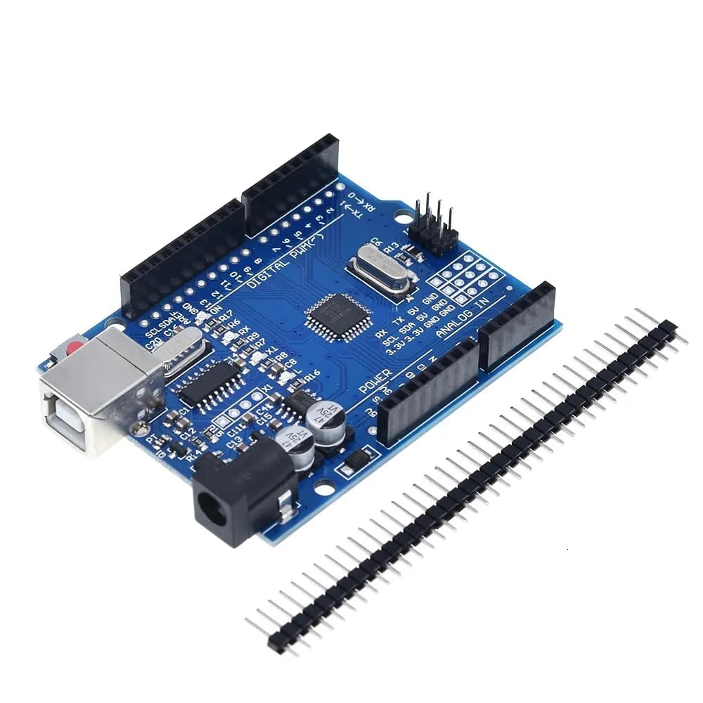
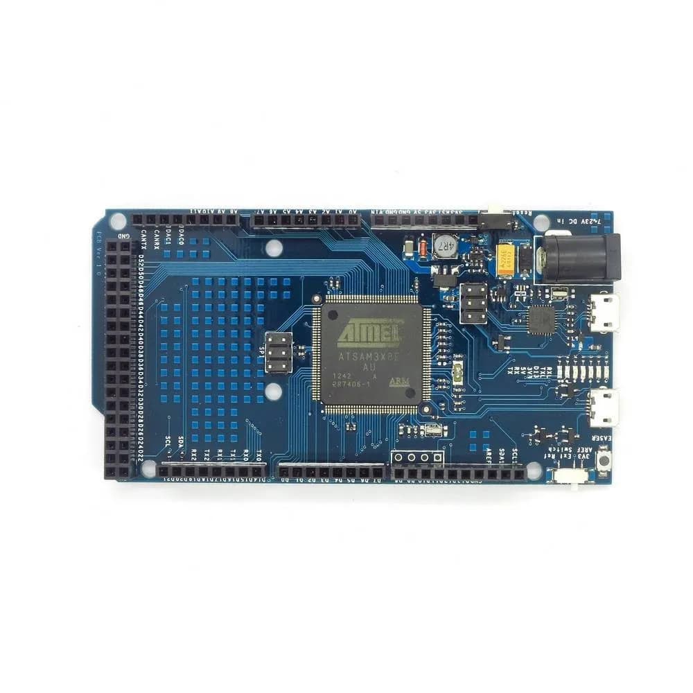
An Arduino Uno has a 10-bit ADC at 5 V: 1024 steps of 4.88 mV, readings 0 to 1023. The ESP32, STM32 and RP2040 are 12-bit at 3.3 V: 4096 steps of 0.81 mV. The ADS1115 is a 16-bit signed converter, so single-ended inputs use 32768 steps of its PGA range, for example 125 µV at ±4.096 V.
With a divider in front (R1 from the source to the pin, R2 from the pin to GND), the source is (R1 + R2) / R2 times the pin voltage. The converter's steps grow by the same factor at the source.
In the bits mode the same value is shown in hex, decimal, octal and binary. Signed numbers use two's complement: in 8 bits the top bit counts as −128, so 0xFF reads as 255 unsigned and −1 signed.
Worked example: a 12 V battery on an Arduino Uno
You measure a 12 V battery on A0 through R1 = 10 kΩ and R2 = 4.7 kΩ, with the Uno's 5 V reference.
- Divider factor
(10 000 + 4 700) / 4 700 = 3.128 - Voltage at the pin
12 / 3.128 = 3.837 V - Expected reading
floor(3.837 × 1024 / 5) = 785 - Back to volts
785 × 5 / 1024 × 3.128 = 11.99 V - Resolution at the battery
5 / 1024 × 3.128 = 15.3 mV
analogRead(A0) returns about 785. The divider lets you read up to 15.6 V, and each count is about 15 mV of battery voltage.
Common mistakes
Dividing by 1023 instead of 1024
The datasheets give V = reading × Vref / 1024. Using 1023 is a small error (0.1%), but it makes the top count read exactly Vref, which the ADC can never measure.
Letting the pin go above the supply
A divider has to keep the pin below the chip's supply even at the highest source voltage. 12 V straight into a 3.3 V pin destroys it.
A divider with huge resistors
Above about 10 kΩ source impedance the ADC's sampling capacitor doesn't charge fully and readings sag. Use smaller resistors or add 100 nF at the pin.
Forgetting read_u16() is scaled
MicroPython's read_u16() returns 0–65535 on every board. Divide by 65536, not by 4096.
Mixing signed and unsigned
A byte 0xFF from a sensor is −1 in an int8_t and 255 in a uint8_t. Reading a signed register into an unsigned type turns small negatives into large positives.
Shifting 1 past bit 30 in C
On a 32-bit int, 1 << 31 overflows. Write 1UL << 31 for the top bit of a 32-bit mask.
Frequently asked questions
Multiply by the reference and divide by the number of steps: volts = analogRead(A0) × 5.0 / 1024 on an Uno. On a 12-bit board at 3.3 V it is × 3.3 / 4096.
The ESP32 ADC is not linear near 0 V and near the top of each attenuation range, and it varies from chip to chip. Stay inside the usable range (about 0.15–2.45 V at 11 dB) and use analogReadMilliVolts(), which applies the factory calibration.
Use a voltage divider so the pin sees at most about 3 V, for example R1 = 10 kΩ and R2 = 3.3 kΩ (factor 4.03). Multiply the pin voltage by the factor in your code.
It is how signed integers are stored. The top bit counts as a negative weight (−128 in 8 bits), so 0x80 is −128, 0xFF is −1 and 0x7F is 127. To negate a number, invert all its bits and add 1.
The order bytes sit in memory. AVR, ESP32 and ARM are little-endian: 0x1234 is stored as 0x34 then 0x12. Network protocols and many sensors send big-endian, the high byte first.
It is a 16-bit signed converter. Single-ended inputs use 0 to 32767, so at ±4.096 V each count is 125 µV; at ±0.256 V it is 7.8 µV.