1. Electronics Tools
  2. LM317 Voltage Regulator Calculator

LM317 Voltage Regulator Calculator

Type the voltage you want and get R1 and R2 you can buy — then check dropout and whether the regulator needs a heatsink.

LM317ADJOUTIN5.0V
Try
V
Ω

Exact R2 is 801.3 Ω → closest E12 value: 820 Ω.

Input and load

Heatsink

Live circuit

Vin12 VVout5.087 V0 V→ 500 mACin 0.1µFCout 1µFLM317INOUTADJR1270 ΩR2820 Ω1.25 V

The LM317 holds 1.25 V across R1; the same current through R2 sets how far above that the output sits. The chip turns red as it heats up.

Output voltage

5.087V

+1.75% from the 5 V you asked for — standard values can't do better in this series.

R1 270 ΩR2 820 Ω
2575125

199 °C

chip temperature

Results

Current through R1/R2
4.63 mA
Minimum input voltage
6.922 V
Heat in the regulator
3.488 W
Efficiency
42 %
  • The chip would reach 199 °C — over its 125 °C limit. Fit a Small clip-on heatsink.
  • Only 42% efficient: 3.488 W becomes heat. A buck converter module would run cool.

Best standard R1/R2 pairs

Values you can buy for 5 V, closest first. R1 stays between 100 Ω and 1 kΩ so the regulator always has its minimum load.

  • R1270 Ω
    R2820 Ω
    5.087 V +1.75%4.63 mA
  • R1330 Ω
    R21 kΩ
    5.088 V +1.76%3.788 mA
  • R1220 Ω
    R2680 Ω
    5.148 V +2.95%5.682 mA
  • R1390 Ω
    R21.2 kΩ
    5.156 V +3.12%3.205 mA
  • R1180 Ω
    R2560 Ω
    5.167 V +3.34%6.944 mA
  • R1150 Ω
    R2470 Ω
    5.19 V +3.80%8.333 mA

Step by step

  1. Vout

    Vout = 1.25 V × (1 + R2 / R1) + Iadj × R2

    = 1.25 V × (1 + 820 Ω ÷ 270 Ω) + 50 µA × 820 Ω = 5.087 V

  2. I

    IR1 = 1.25 V / R1

    = 1.25 V ÷ 270 Ω = 4.63 mA

  3. P

    P = (Vin − Vout) × (Iload + IR1)

    = (12 V − 5.087 V) × 504.6 mA = 3.488 W

  4. Tj

    Tj = 25 °C + P × θ

    = 25 °C + 3.488 W × 50 °C/W = 199 °C

Good to know

Add the capacitors

0.1 µF on the input close to the pins, 1 µF or more on the output. A 10 µF from ADJ to ground cuts ripple further.

The tab is the output

The metal tab is connected to OUT. Use an insulating pad and washer if the heatsink touches anything else.

Protection diodes

With big output capacitors, a 1N4002 from OUT to IN (and from ADJ to OUT) protects the chip when the input is shorted.

Linear means heat

Everything between Vin and Vout is burnt: P = (Vin − Vout) × I. For big drops or currents, a buck module is far cooler.

How the LM317 sets its voltage

The LM317 keeps exactly 1.25 V between OUT and ADJ. That fixes the current through R1 (1.25 V ÷ R1), and the same current flows down R2, so Vout = 1.25 V × (1 + R2/R1). The small ADJ pin current (about 50 µA) adds Iadj × R2 — included here — which is why R1 is kept small (120–240 Ω).

How to set an LM317 output voltage

How the LM317 formula works

Vout = 1.25 × (1 + R2 / R1) + Iadj × R2

The LM317 keeps 1.25 V between its OUT and ADJ pins. R1 sits across that reference, so a fixed current flows through it and on through R2; the voltage across R2 is added to the 1.25 V. The small current out of the ADJ pin (Iadj, about 50 µA) adds a few tens of millivolts.

R1 is usually between 120 Ω and 240 Ω so the divider alone draws the few milliamps the regulator needs to stay in regulation with no load. The calculator tries every standard R1 from 100 Ω to 1 kΩ and lists the pairs closest to your target.

The regulator needs about 1.7 V to 2.3 V more at its input than at its output (the dropout), and everything in between turns into heat: P = (Vin − Vout) × I. A TO-220 package with no heatsink reaches its 125 °C limit at only around 2 W.

Worked example: 5 V at 500 mA from a 12 V adapter

You want 5 V for a 500 mA load, starting from the classic R1 = 240 Ω.

  1. Exact R2 for 240 ΩR2 = (5 − 1.25) / (1.25/240 + 50 µA) ≈ 713 Ω
  2. Closest E12 pair (R1 = 270 Ω, R2 = 820 Ω)1.25 × (1 + 820/270) + 50 µA × 820 ≈ 5.09 V
  3. Minimum input voltage5 V + 1.84 V dropout ≈ 6.84 V
  4. Heat from a 12 V input(12 − 5) × 0.5 A = 3.5 W

With 270 Ω and 820 Ω you get about 5.09 V. At 3.5 W the bare package would reach about 200 °C, so a heatsink is required (a small one brings it down to about 95 °C), or use a lower input voltage.

Common mistakes

  • Swapping R1 and R2

    R1 goes between OUT and ADJ, R2 between ADJ and ground. Swapped, 240 Ω/720 Ω gives about 1.7 V instead of 5 V.

  • Forgetting the dropout

    A 5 V USB input cannot give 5 V out: the LM317 needs roughly 2 V of headroom. Below that the output just follows the input minus the dropout.

  • Ignoring the heat

    Dropping 12 V to 5 V at 1 A means 7 W of heat. Beyond 1 W to 2 W use a heatsink, and for large drops consider a buck converter instead.

  • Choosing R1 too large

    With R1 at several kilohms the divider no longer provides the regulator's minimum load, and the output rises when the load is disconnected. Keep R1 at or below about 240 Ω if the load can be absent.

LM317 FAQ

R1 = 240 Ω with R2 = 720 Ω (two parts, or a trimmer) gives about 5.0 V. With single E12 values, 270 Ω and 820 Ω give about 5.09 V.

R1 = 240 Ω and R2 = 390 Ω give about 3.30 V. The ESP32 and other 3.3 V boards are fine with that, but a dedicated 3.3 V LDO wastes less power.

The output voltage plus the dropout, about 1.7 V at light load and up to about 2.3 V at 1.5 A. For 12 V out at 1 A, feed it at least 14 V to 15 V.

Multiply the voltage it drops by the current: (Vin − Vout) × I. Up to about 1 W a bare TO-220 is fine; around 2 W it reaches its limit; above that use a heatsink sized for the power.

1.5 A for the TO-220 version, as long as the heat stays within limits. The small TO-92 LM317L is limited to 100 mA.

Free shipping

On orders over 5000DA

Easy returns

7-day hassle-free returns

Fast checkout

payments on delivery and fast shipping

24/7 support

We're here to help

Dzduino Online Store

Eempowering engineers, students, makers, researchers, and businesses with high-quality and innovative technical solutions.

  • Sales: store@dzduino.com
  • Store: +213 550 88 88 27
  • Sales: +213 550 88 88 29
  • Support: +213 550 88 88 37
  • 043 Cite Remila (Route du Port), Tigditt - Mostaganem

Shop

  • All Categories
  • Électronique & Développement
  • Tools & Equipements & DIY
  • Téléphonie & Communication
  • Fabrication & Prototyping
  • Computers & Networks
  • Power & Energy & Solar
  • Video Surveillance & Security systems
  • Educational, Scientific and Laboratory

Support

  • Track order
  • Orders
  • Account
  • Shipping & returns
  • Shipping calculator

Company

  • About
  • Contact us
  • Site map
  • Privacy
  • Terms

Stay in the loop

New stock, maker deals, and electronics tips — straight to your inbox.

© 2026 Dzduino Electronics, All Rights Reserved

TermsPrivacyShipping & returnsSite map
CIBBARIDI MobFawriPayCash
Free express shipping on orders over 10,000DA
SpecialSaleBlogPrint & CutLabContact usToolsNewLabNew

Related products

Boards, modules, and kits that pair with this tool.

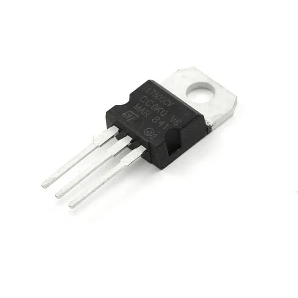
78xx Voltage Regulator -  5, 9, 12 V
DZD00022330

78xx Voltage Regulator - 5, 9, 12 V

FromDZD 5.00In StockIn Stock
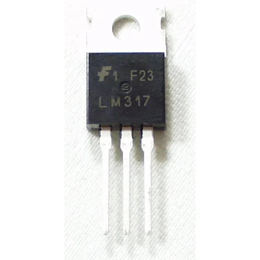
LM317T LM317 Voltage Regulator IC 1.2V to 37V 1.5A
DZD0002241

LM317T LM317 Voltage Regulator IC 1.2V to 37V 1.5A

DZD 80.00In StockIn Stock
IRF5305 Mosfet 31A/55V (P-CHANNEL)
DZD00022530

IRF5305 Mosfet 31A/55V (P-CHANNEL)

DZD 150.00In StockIn Stock
IRF644 P-Channel MOSFET 14A/250V
DZD00022699

IRF644 P-Channel MOSFET 14A/250V

DZD 150.00In StockIn Stock
AMS1117 SOT 223 Voltage Regulator
DZD002210404

AMS1117 SOT 223 Voltage Regulator

DZD 40.00In StockIn Stock
IRF540NPBF TO-220 MOS
DZD00269553

IRF540NPBF TO-220 MOS

DZD 120.00In StockIn Stock
79xx Negative Voltage Regulator
DZD00275122

79xx Negative Voltage Regulator

DZD 90.00In StockIn Stock
A3144E Hall sensor
DZD0033440

A3144E Hall sensor

DZD 50.00Out of StockOut of Stock
View all